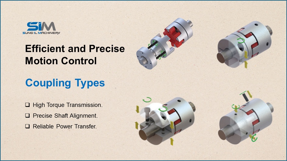
The SUNG-IL MACHINERY coupling selection guide provides a practical step-by-step process for choosing the right coupling based on motor characteristics, operating torque, shaft dimensions, and slip torque. Following the correct coupling selection process helps ensure reliable power transmission, stable operation, and compatibility between driving and driven shafts across various industrial applications.
Step 1: Select the Coupling Type
The first step in this coupling selection guide is choosing the appropriate coupling type based on the coupling characteristics and the type of connected motor. Different coupling designs are suitable for different operating requirements, making the correct type an important factor in achieving reliable performance.
Special operating environments may require additional consideration. Applications involving vacuum environments, high temperatures, cleanroom facilities, or other special conditions may require specific materials or coupling configurations. For these applications, the operating environment should be considered when selecting the most suitable coupling.
Step 2: Select the Coupling Outer Diameter (OD)
Once the coupling type has been selected, determine the required outer diameter (OD) based primarily on the motor’s operating torque. The rated torque of the selected coupling should be higher than the motor’s operating torque.
The appropriate safety factor may vary depending on the application and customer requirements. Motor operating torque can generally be obtained from the motor specifications. Selecting an appropriate OD size with sufficient torque capacity helps support reliable power transmission and stable operation.
Step 3: Check the Maximum Inner Diameter (ID)
The third step in the coupling selection guide is checking the maximum inner diameter (ID). Both the driving and driven shaft diameters must be within the allowable maximum ID range of the selected coupling.
If either shaft diameter exceeds the maximum ID, a larger coupling size should be selected. For example, if an SDS-19C coupling is selected in Step 2 but the shaft diameter is 8 mm while the maximum ID is 6 mm, the coupling should be increased to an SDS-22C.
Checking the shaft dimensions ensures proper coupling compatibility and helps achieve a secure connection between the driving and driven components.
Step 4: Check the Slip Torque
The final step of the coupling selection guide is checking the slip torque for the selected inner diameters. Slip torque values should be compared with the motor’s operating torque using the dimensions and performance specifications.
For example, suppose an SDS-22C coupling with 4 mm × 8 mm inner diameters is selected. If the maximum torque of the coupling is 2.2 N·m and the slip torque at the 4 mm ID is 1.4 N·m, the 1.4 N·m slip torque must be compared with the actual operating torque.
If the slip torque is lower than the operating torque, there may be a risk of slipping during operation. In such cases, a larger coupling size should be considered, or an additional solution such as a key or keyway may be required for safer operation.
Industrial Coupling Selection
A properly selected coupling provides a reliable mechanical connection between rotating components while supporting efficient torque transmission. By following the four key stages of this coupling selection guide—coupling type, outer diameter, inner diameter, and slip torque—engineers can determine a suitable coupling configuration for their specific application.
Considering motor specifications, operating torque, shaft dimensions, environmental conditions, and slip torque together helps ensure reliable coupling performance and long-term operation in industrial drive systems.
If you are looking for coupling selection guide, you can find them at SUNG-IL MACHINERY.
Click here to learn more about SUNG-IL MACHINERY products.
View more: Industrial Coupling Selection Guide